Focused Linear scan with L7-4 probe in Verasonics demonstrating RTB
This script is available in the USTB repository as examples/uff/FI_UFF_Verasonics_linear_RTB.m
This example demonstrates the RTB implementation and demonstrates different fixes to the artifact occuring near the focus.
One solution is the transmit delay model introduced in Nguyen, N. Q., & Prager, R. W. (2016). High-Resolution Ultrasound Imaging With Unified Pixel-Based Beamforming. IEEE Trans. Med. Imaging, 35(1), 98-108.
Another solution is a simpler model assuming PW around focus.
This scripts creates the figure used in the abstract submitted to the IEEE IUS 2018 with title "A simple, artifact-free virtual source model"
_by Ole Marius Hoel Rindal olemarius@olemarius.net Last updated: 2018/10/05
Contents
Read channel data
clear all; close all;

% data location
url='http://ustb.no/datasets/';      % if not found downloaded from here

filename='L7_FI_IUS2018.uff';
tools.download(filename, url, data_path);
channel_data=uff.read_object([data_path filesep filename],'/channel_data');
UFF: reading channel_data [uff.channel_data]
UFF: reading sequence [uff.wave] [====================] 100%
Define Scan
x_axis=zeros(channel_data.N_waves,1);
for n=1:channel_data.N_waves
    x_axis(n)=channel_data.sequence(n).source.x;
end
z_axis=linspace(1e-3,62e-3,512*2).';
scan=uff.linear_scan('x_axis',x_axis,'z_axis',z_axis);
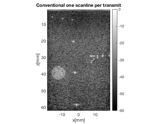
Conventional Scanline Beamforming
mid=midprocess.das();
mid.dimension = dimension.both();

mid.channel_data=channel_data;
mid.scan=scan;

mid.transmit_apodization.window=uff.window.scanline;

mid.receive_apodization.window=uff.window.none;
mid.receive_apodization.f_number=1.7;

b_data=mid.go();
USTB General beamformer MEX v1.1.2 .............done!
Display image
b_data.plot([],'Conventional one scanline per transmit');
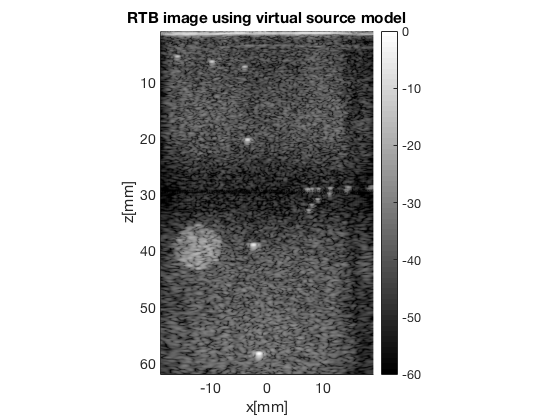
Retrospective beamforming (RTB) with conventional virtual source model
Create scan with MLA's
MLA = 4;
scan_RTB=uff.linear_scan('x_axis',linspace(x_axis(1),x_axis(end),...
                                    length(x_axis)*MLA)','z_axis',z_axis);

% beamform without any fix using conventional virtual source model
mid_RTB=midprocess.das();
mid_RTB.dimension = dimension.both();

mid_RTB.channel_data=channel_data;
mid_RTB.scan=scan_RTB;

mid_RTB.transmit_apodization.window=uff.window.tukey50;
mid_RTB.transmit_apodization.f_number = 3;
mid_RTB.transmit_apodization.MLA = MLA;
mid_RTB.transmit_apodization.MLA_overlap = MLA;

mid_RTB.receive_apodization.window=uff.window.boxcar;
mid_RTB.receive_apodization.f_number=1.7;
b_data_RTB=mid_RTB.go();

b_data_RTB.plot(767,'RTB image using virtual source model');
USTB General beamformer MEX v1.1.2 .............done!
We need to compensate with the TX transmit apodization as weighting to get a more uniform image
% Calculate the transmit apodzation used to compensate image
tx_apod = mid_RTB.transmit_apodization.data;

b_data_RTB_weighted = uff.beamformed_data(b_data_RTB);
b_data_RTB_weighted.data = b_data_RTB_weighted.data.*(1./sum(tx_apod,2));
b_data_RTB_weighted.plot(10,'RTB image using virtual source model, TX weighted');
uff.apodization: Inputs and outputs are unchanged. Skipping process.
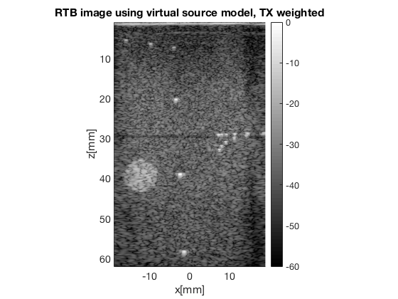
Notice the darker right side. Not sure why this occurs, it is not there for conventional scanline beamforming, and not for MLA's. Could it be that the elemets to the right of the probe are weaker? I'll investigate this further...
Also notice the line/articat along 29.6 mm, the transmit focus, which is the artifact we aimt get rid of :)
RTB using Nguyen & Prager model
beamforming using the "unified pixelbased beamforming" model from Nguyen, N. Q., & Prager, R. W. (2016). High-Resolution Ultrasound Imaging With Unified Pixel-Based Beamforming. IEEE Trans. Med. Imaging, 35(1), 98-108.
mid_RTB_unified_fix =midprocess.das();
mid_RTB_unified_fix.dimension = dimension.both();

mid_RTB_unified_fix.channel_data=channel_data;
mid_RTB_unified_fix.scan=scan_RTB;
mid_RTB_unified_fix.use_unified_fix = 1; %When this flat is set this model is used

mid_RTB_unified_fix.transmit_apodization.window=uff.window.tukey50;
mid_RTB_unified_fix.transmit_apodization.f_number = 3;
mid_RTB_unified_fix.transmit_apodization.MLA = MLA;
mid_RTB_unified_fix.transmit_apodization.MLA_overlap = 1;

mid_RTB_unified_fix.receive_apodization.window=uff.window.boxcar;
mid_RTB_unified_fix.receive_apodization.f_number=1.7;
b_data_RTB_unified_fix=mid_RTB_unified_fix.go();

% Calculate the transmit apodzation used to compensate image
tx_apod = mid_RTB_unified_fix.transmit_apodization.data;

b_data_RTB_unified_fix_weighted = uff.beamformed_data(b_data_RTB_unified_fix);
b_data_RTB_unified_fix_weighted.data = b_data_RTB_unified_fix_weighted.data...
                                                        .*(1./sum(tx_apod,2));
b_data_RTB_unified_fix_weighted.plot(11,'RTB image Nguyen & Prager mode');
USTB General beamformer MEX v1.1.2 .............done!
uff.apodization: Inputs and outputs are unchanged. Skipping process.
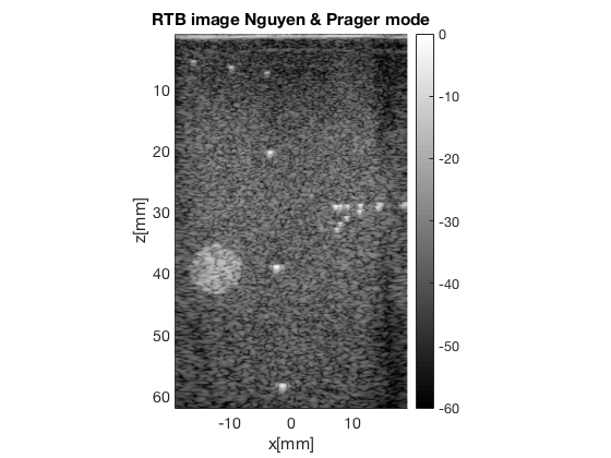
Their model sucessfully removes the artifact at focus (29.6 mm)!
RTB using a simpler model assuming PW around focus
mid_RTB_with_plane_fix=midprocess.das();
mid_RTB_with_plane_fix.dimension = dimension.both();
mid_RTB_with_plane_fix.use_PW_fix = 1; % Set this flag to use this model
%Optionally set the margin of the region around focus to use PW tx delay
mid_RTB_with_plane_fix.margin_in_m = 1/1000;

mid_RTB_with_plane_fix.channel_data=channel_data;
mid_RTB_with_plane_fix.scan=scan_RTB;

mid_RTB_with_plane_fix.transmit_apodization.window=uff.window.tukey50;
mid_RTB_with_plane_fix.transmit_apodization.f_number = 3;
mid_RTB_with_plane_fix.transmit_apodization.MLA = MLA;
mid_RTB_with_plane_fix.transmit_apodization.MLA_overlap = 1;

mid_RTB_with_plane_fix.receive_apodization.window=uff.window.boxcar;
mid_RTB_with_plane_fix.receive_apodization.f_number=1.7;
b_data_RTB_with_plane_fix=mid_RTB_with_plane_fix.go();

% Calculate the transmit apodzation used to compensate image
tx_apod = mid_RTB_with_plane_fix.transmit_apodization.data;

b_data_RTB_plane_fix_weighted = uff.beamformed_data(b_data_RTB_with_plane_fix);
b_data_RTB_plane_fix_weighted.data = b_data_RTB_plane_fix_weighted.data...
                                                        .*(1./sum(tx_apod,2));
b_data_RTB_plane_fix_weighted.plot(10,'RTB image with PW hybrid virtual source model');
USTB General beamformer MEX v1.1.2 .............done!
uff.apodization: Inputs and outputs are unchanged. Skipping process.

Our simplified model also removes the artifact
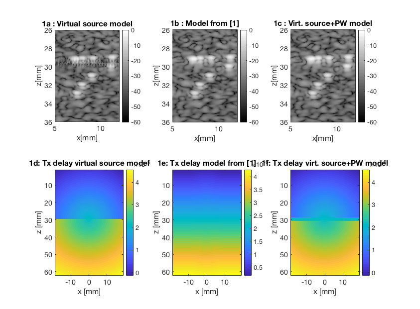
Create plot to be used in abstract showing the images and the TX delays
The images can be zoomed in on the artifact as we did in the abstract, and we can see that both the Nguyen & Prager model, and our simple PW model sucessfully removes the artifact at focus.
% We are plotting the TX delay used for the center transmit beam
tx_delay_virtual_source = reshape(mid_RTB.tx_delay_hack,scan_RTB.N_z_axis,...
                                    scan_RTB.N_x_axis,channel_data.N_waves);
tx_delay_unified_fix = reshape(mid_RTB_unified_fix.tx_delay_hack,scan_RTB.N_z_axis,...
                                    scan_RTB.N_x_axis,channel_data.N_waves);
tx_delay_plane_fix = reshape(mid_RTB_with_plane_fix.tx_delay_hack,scan_RTB.N_z_axis,...
                                    scan_RTB.N_x_axis,channel_data.N_waves);

h = figure(100);clf;
b_data_RTB_weighted.plot(subplot(2,3,1),'1a : Virtual source model');
ax(1) = gca;
b_data_RTB_unified_fix_weighted.plot(subplot(2,3,2),'1b : Model from [1]');
ax(2) = gca;
b_data_RTB_plane_fix_weighted.plot(subplot(2,3,3),'1c : Virt. source+PW model');
ax(3) = gca;
linkaxes(ax);
axis([5 12 26 36])

subplot(2,3,4); imagesc(scan_RTB.x_axis*1000, scan_RTB.z_axis*1000, ...
                    tx_delay_virtual_source(:,:,channel_data.N_waves/2));
title('1d: Tx delay virtual source model');xlabel('x [mm]');ylabel('z [mm]');
colorbar; set(gca,'fontsize',14);
subplot(2,3,5); imagesc(scan_RTB.x_axis*1000, scan_RTB.z_axis*1000, ...
                            tx_delay_unified_fix(:,:,channel_data.N_waves/2));
title('1e: Tx delay model from [1]');xlabel('x [mm]');ylabel('z [mm]');
colorbar; set(gca,'fontsize',14);
subplot(2,3,6); imagesc(scan_RTB.x_axis*1000, scan_RTB.z_axis*1000, ....
                            tx_delay_plane_fix(:,:,channel_data.N_waves/2));
title('1f: Tx delay virt. source+PW model');xlabel('x [mm]');ylabel('z [mm]');
colorbar; set(gca,'fontsize',14);%colormap jet;

set(h,'Position',[271    38   843   621]);

% A few trics to get the colormap in the submitted abstract:
% 1. Run the three bottom subplots with colormap jet
% 2. Rerun the three first subplots to get colormap gray